Frame rail · standard model
APU assembly
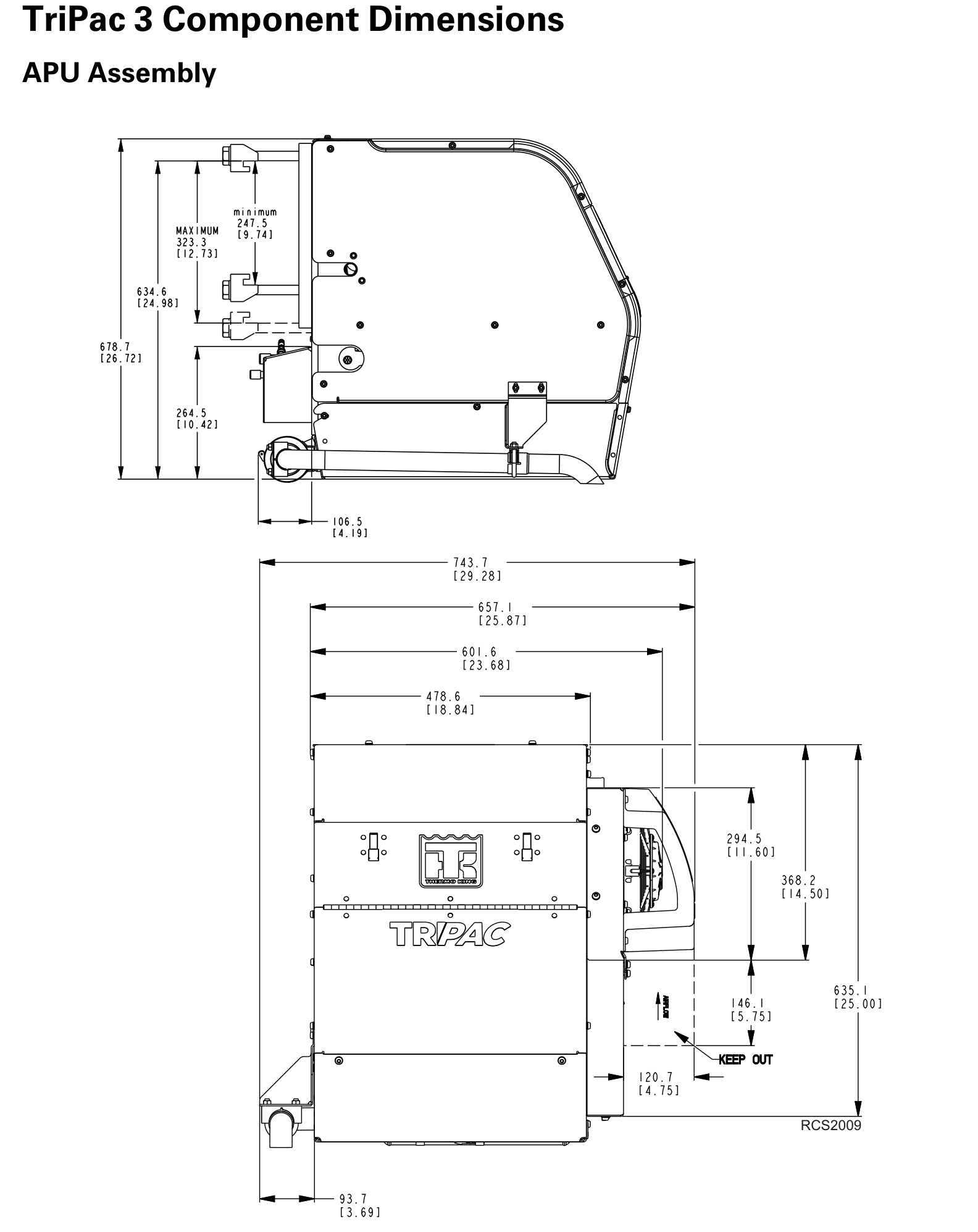
The drawing shows a 29.28 in (743.7 mm) overall span in the illustrated front view. Allow for the mounting arrangement, exhaust and service access.
TriPac installation planning
Explore where the components go, see Thermo King’s drawings, and start a better conversation about your truck.
← Back to TriPac sales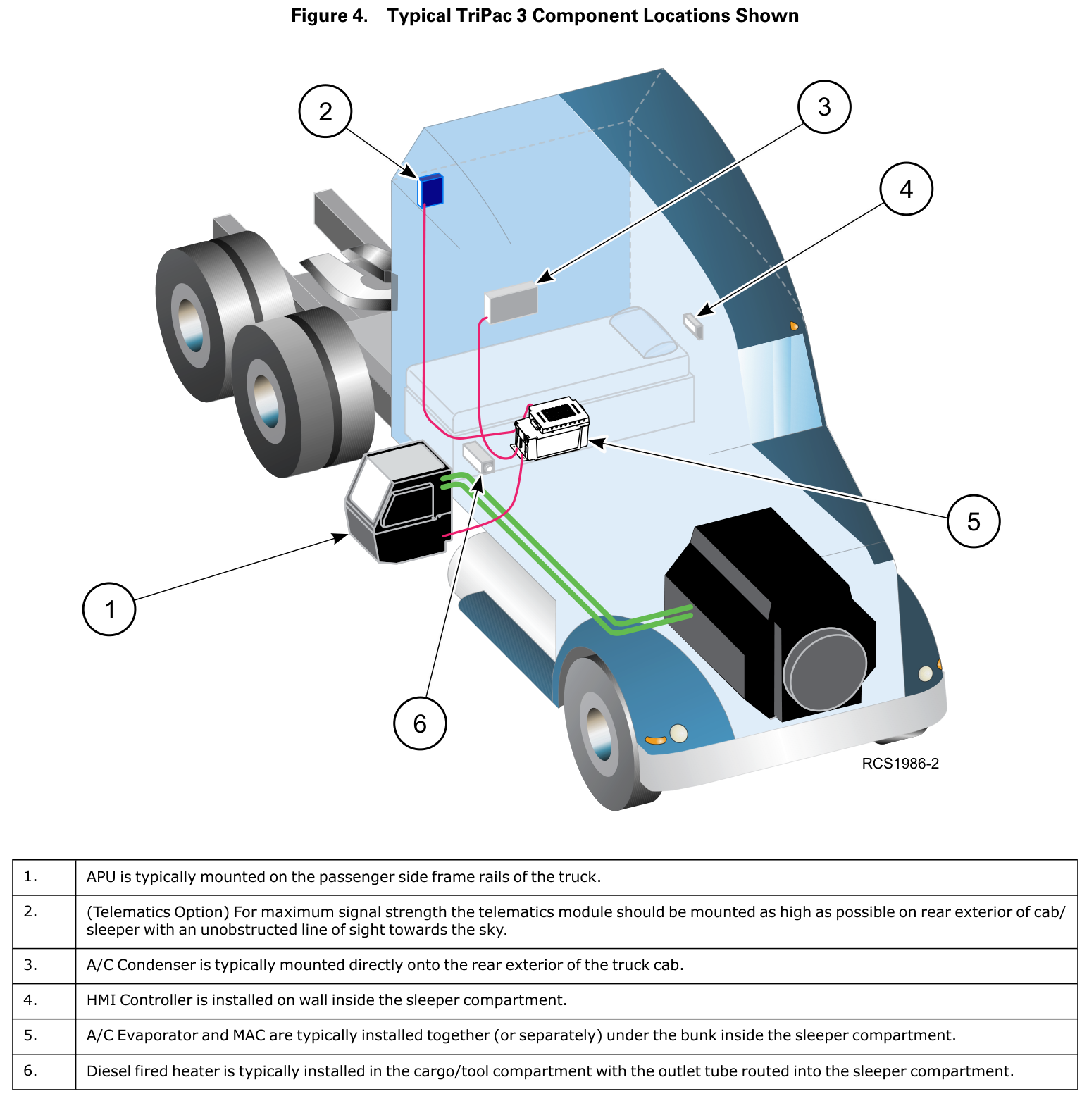
Diesel auxiliary power
Start with the frame-mounted APU and follow the system into the sleeper. Select a drawing to enlarge it.
Where it goes
The APU typically sits on the passenger-side frame rail, the condenser on the rear of the cab, and the evaporator/MAC under the bunk. The heater and controller need their own locations.
The aftertreatment configuration and truck layout affect the space required.
View the TriPac 3 dimensions PDFEnlarge component locations ↗Frame rail · standard model
The drawing shows a 29.28 in (743.7 mm) overall span in the illustrated front view. Allow for the mounting arrangement, exhaust and service access.
Frame rail · ATD model
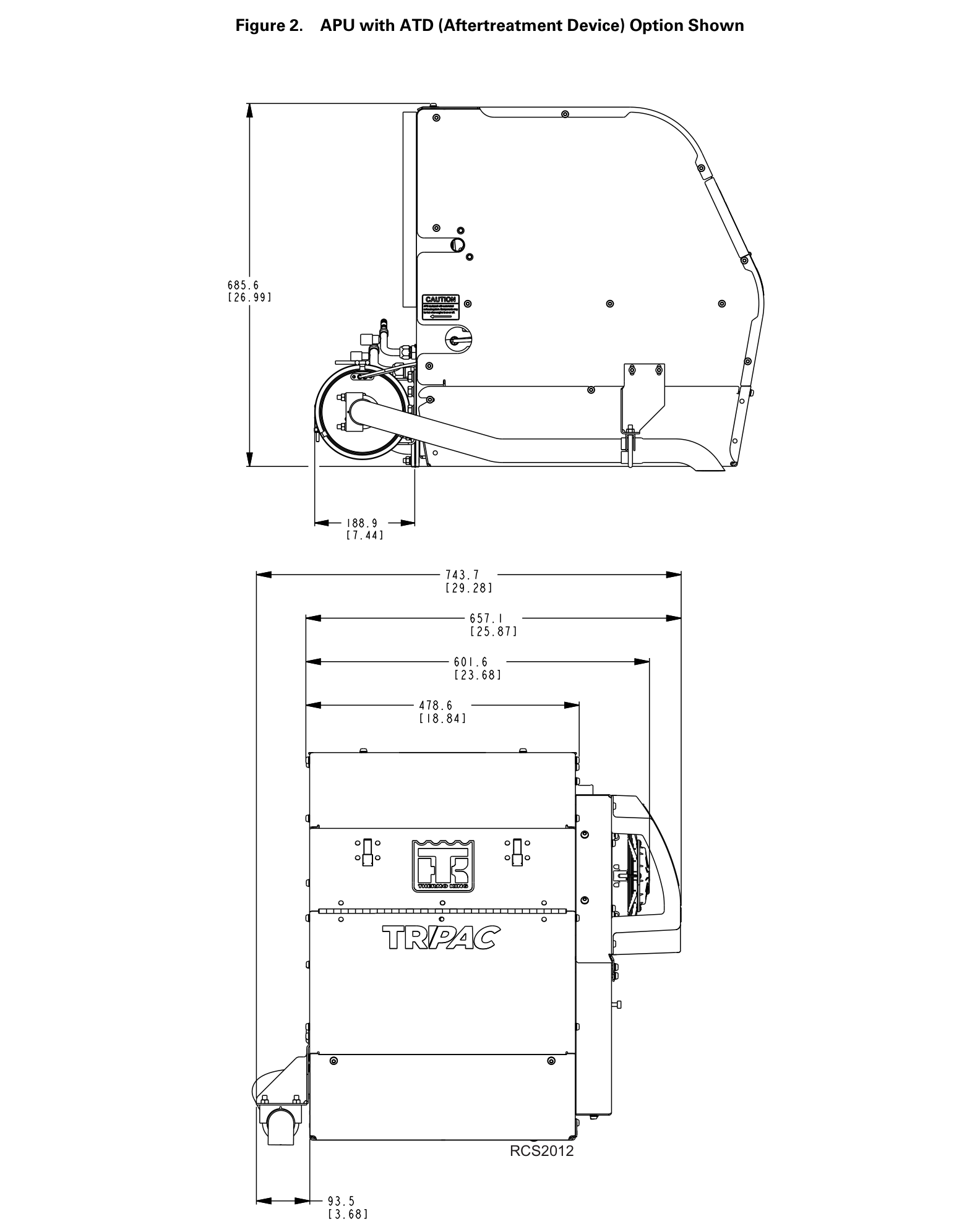
The ATD changes the package around the power unit. The shown front-view overall span is 29.28 in (743.7 mm); use the drawing and truck-specific clearances when planning.
Rear exterior of cab
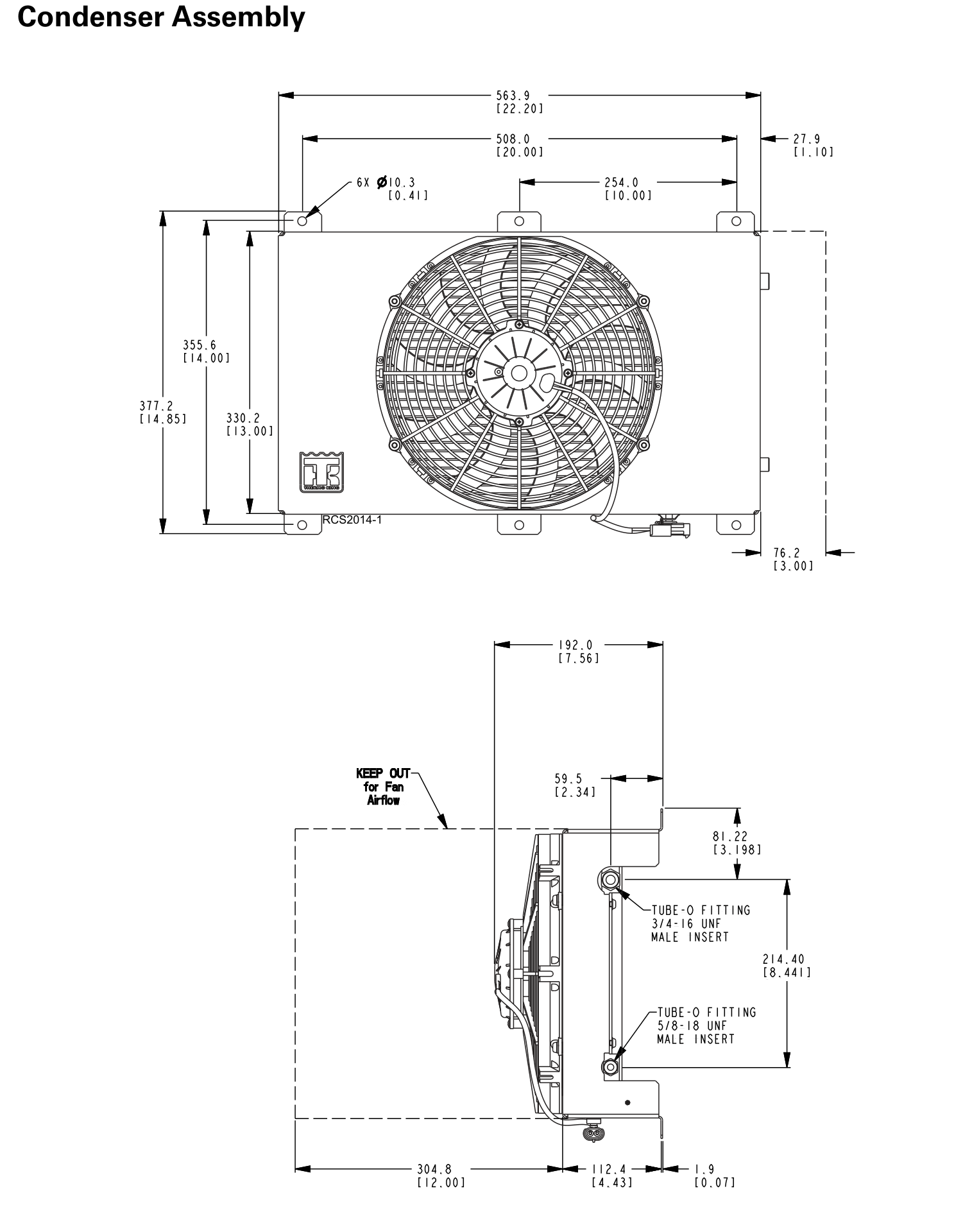
The drawing shows a 22.20 in (563.9 mm) horizontal span and 14.85 in (377.2 mm) mounting-tab height. The fan also needs its specified airflow keep-out area.
Typically under the bunk
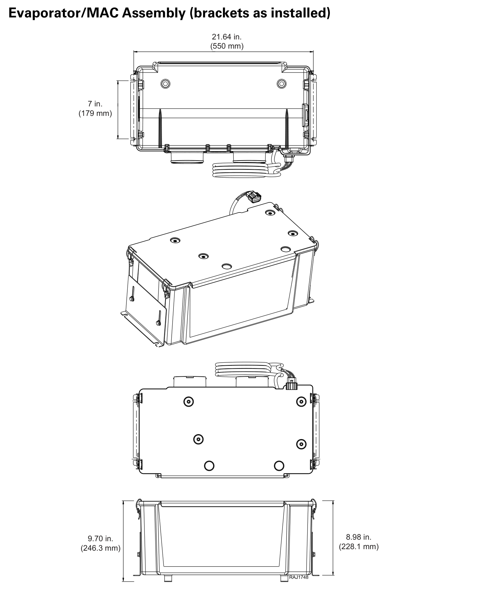
The installed-bracket drawing shows a 21.64 in (550 mm) span. Check the other views for the installed height, fittings and space for ducting.
Sleeper storage / tool compartment
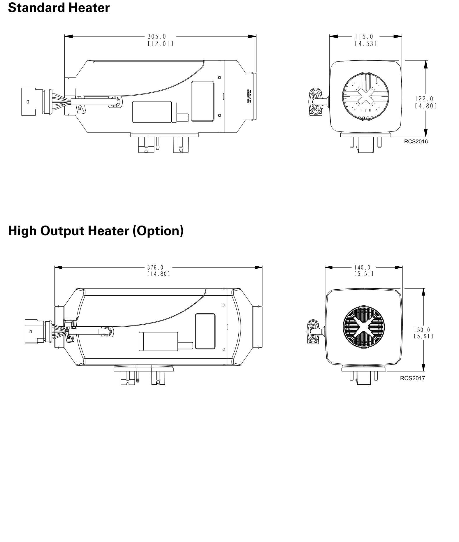
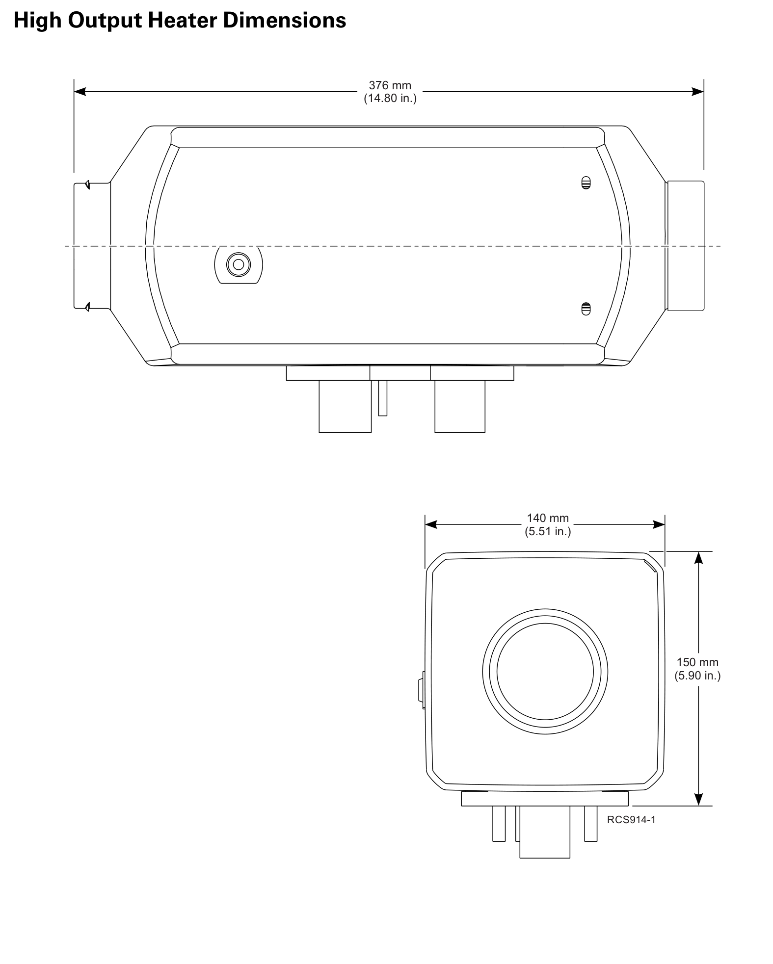
Standard heater: 12.01 × 4.53 × 4.80 in (305 × 115 × 122 mm). High-output option: 14.80 × 5.51 × 5.91 in (376 × 140 × 150 mm).
Sleeper wall
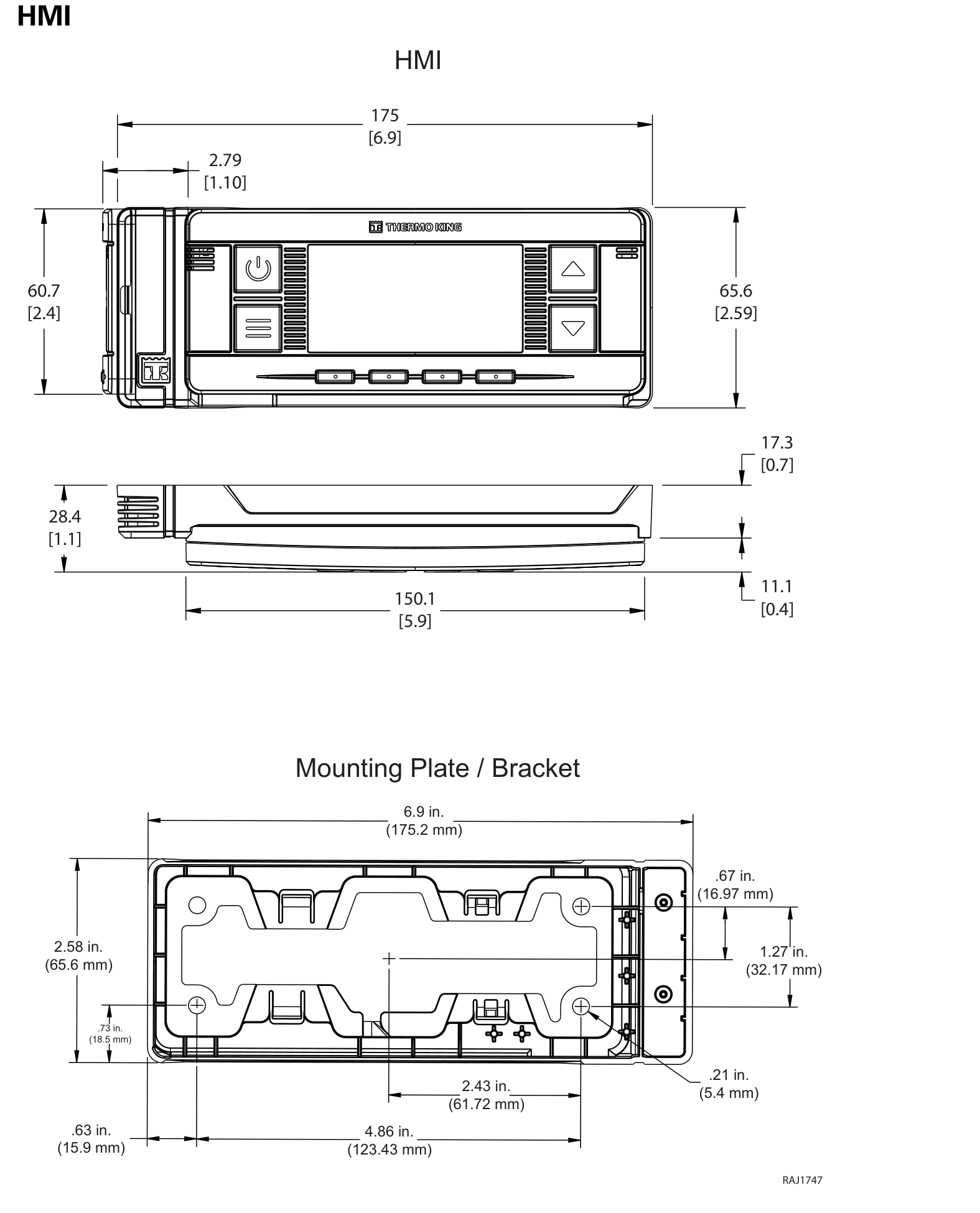
The TriPac 3 HMI drawing shows a 6.9 in (175 mm) face width. Leave room for the mounting plate, wiring and driver access.
Available electrical option
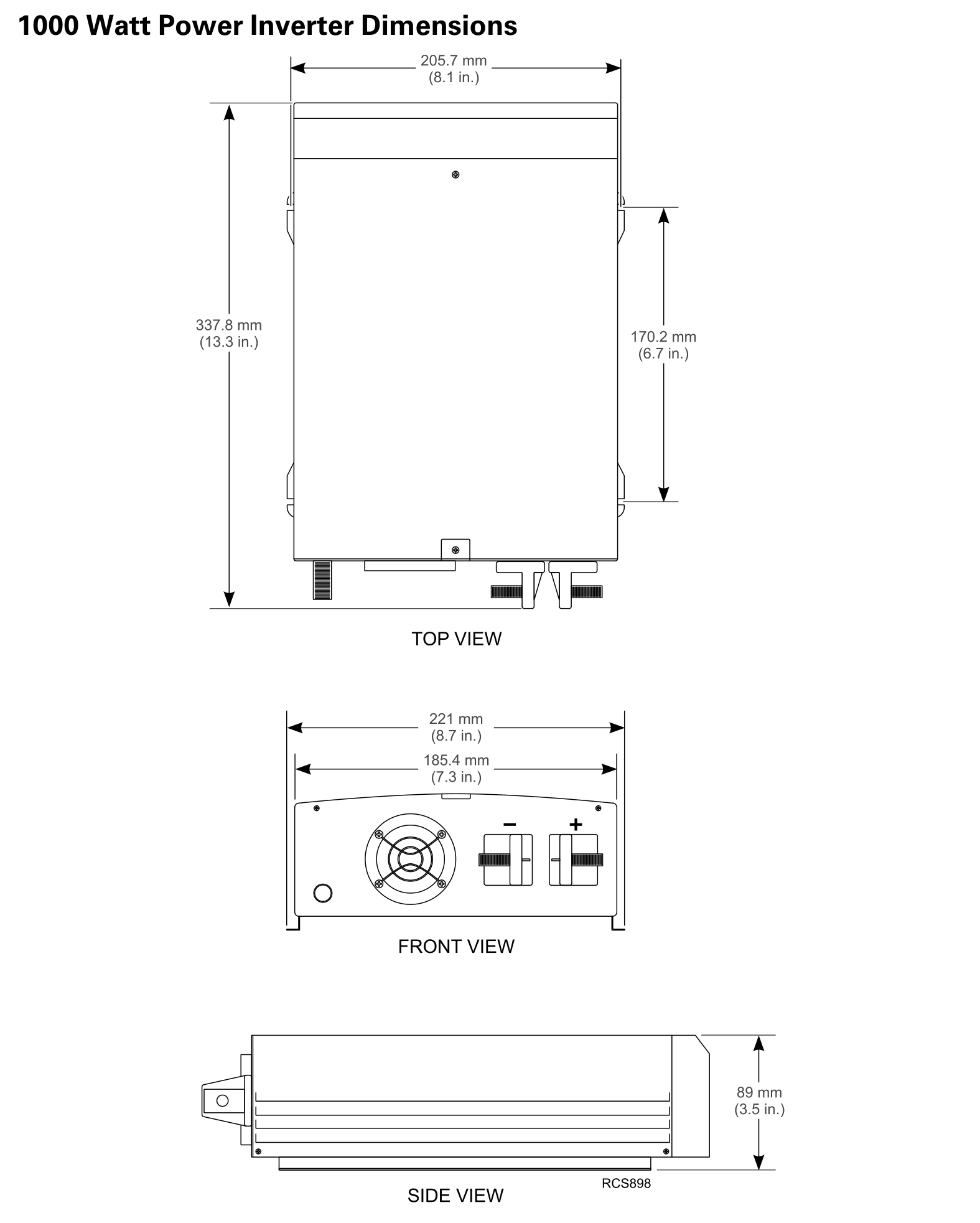
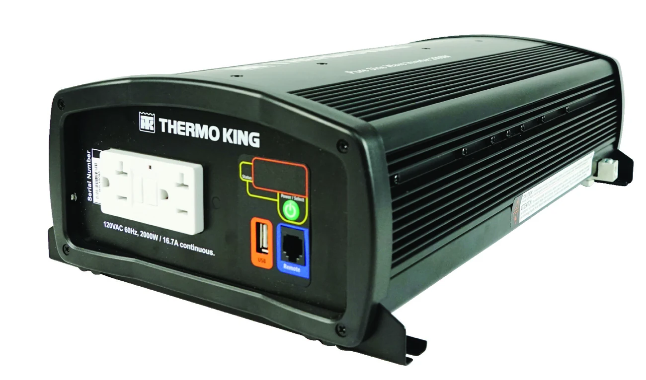
For Thermo King inverter model 452855, the operator’s manual lists 16.378 × 9.055 × 4.43 in (L × W × H). Confirm the inverter model and required ventilation for your installation.
Battery-electric auxiliary power
Make room for the battery box, cab components and any selected charging or power accessories.
Where it goes
The battery box mounts on the truck, with the condenser behind the cab and the evaporator/control box typically under the bunk. The available heater, shore-power equipment and inverter require additional planning.
View the Envidia 2 dimensions PDF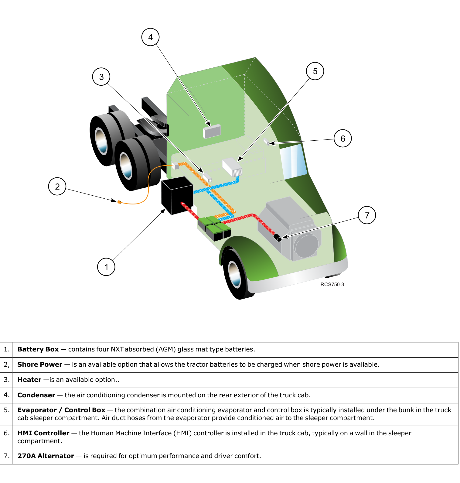 Enlarge component locations ↗
Truck frame
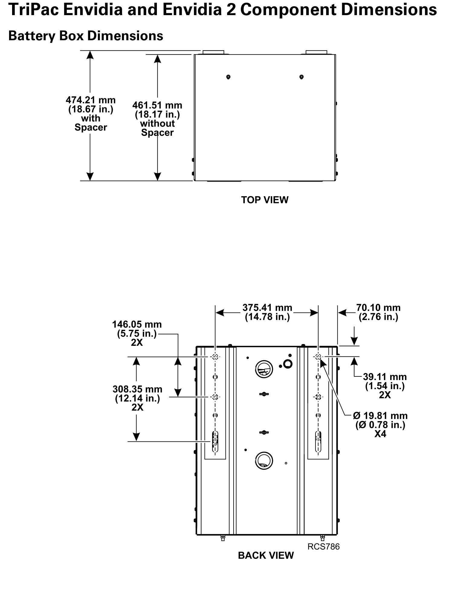
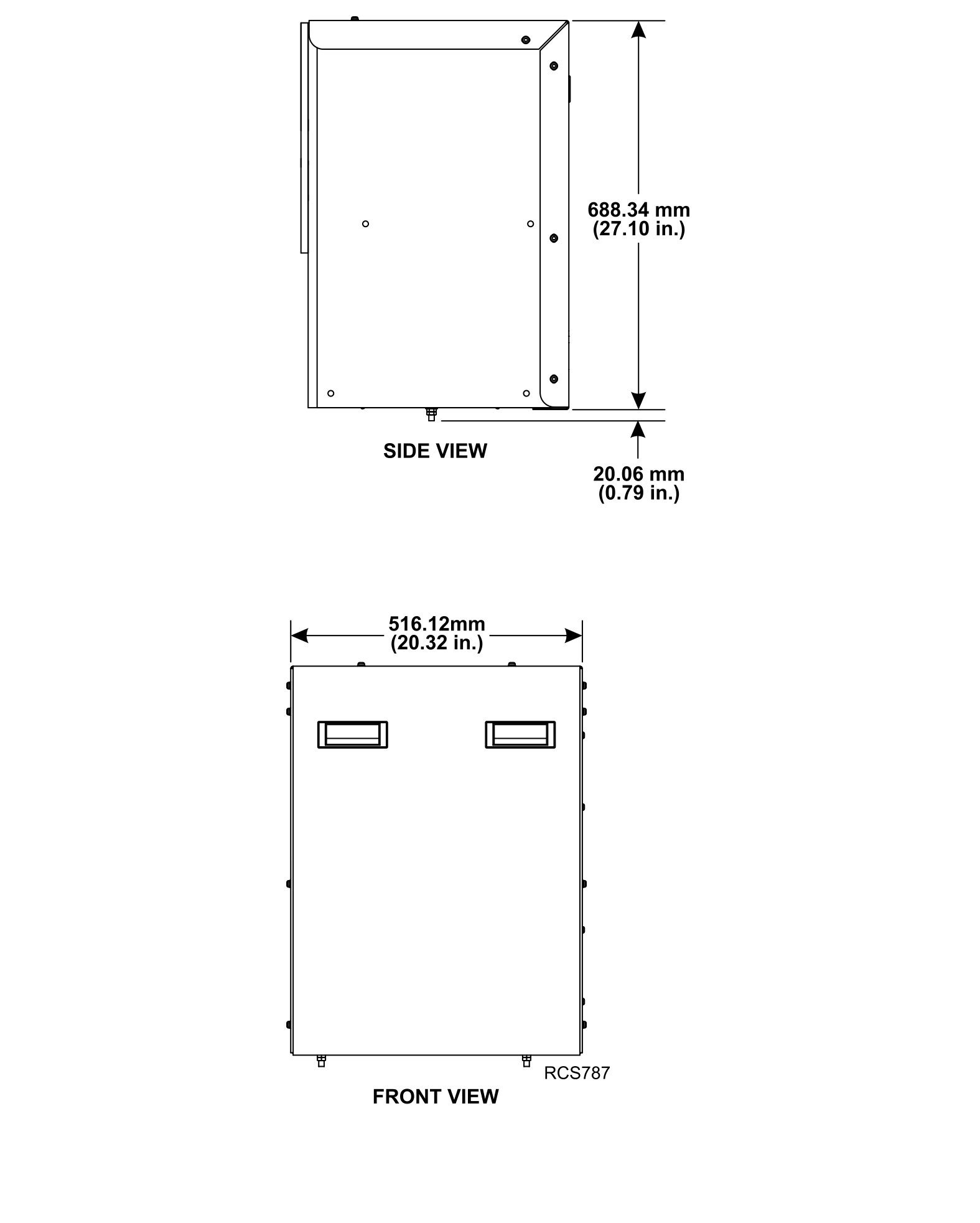
Front-view width is 20.32 in (516.12 mm), height is 27.10 in (688.34 mm), and the top-view depth is 18.17 in (461.51 mm) without the spacer or 18.67 in (474.21 mm) with it.
Rear exterior of cab
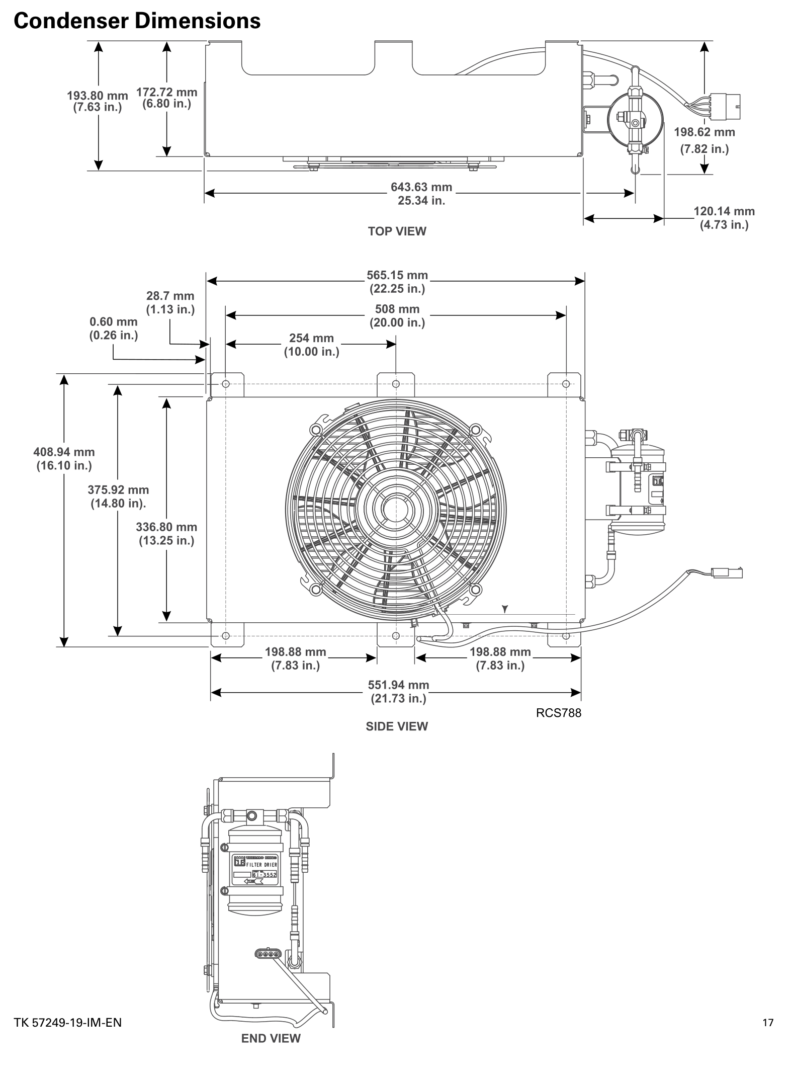
The condenser drawing shows a 22.25 in (565.15 mm) face span and a 16.10 in (408.94 mm) overall height including mounting tabs. The drier and fittings extend beyond the face.
Typically under the bunk
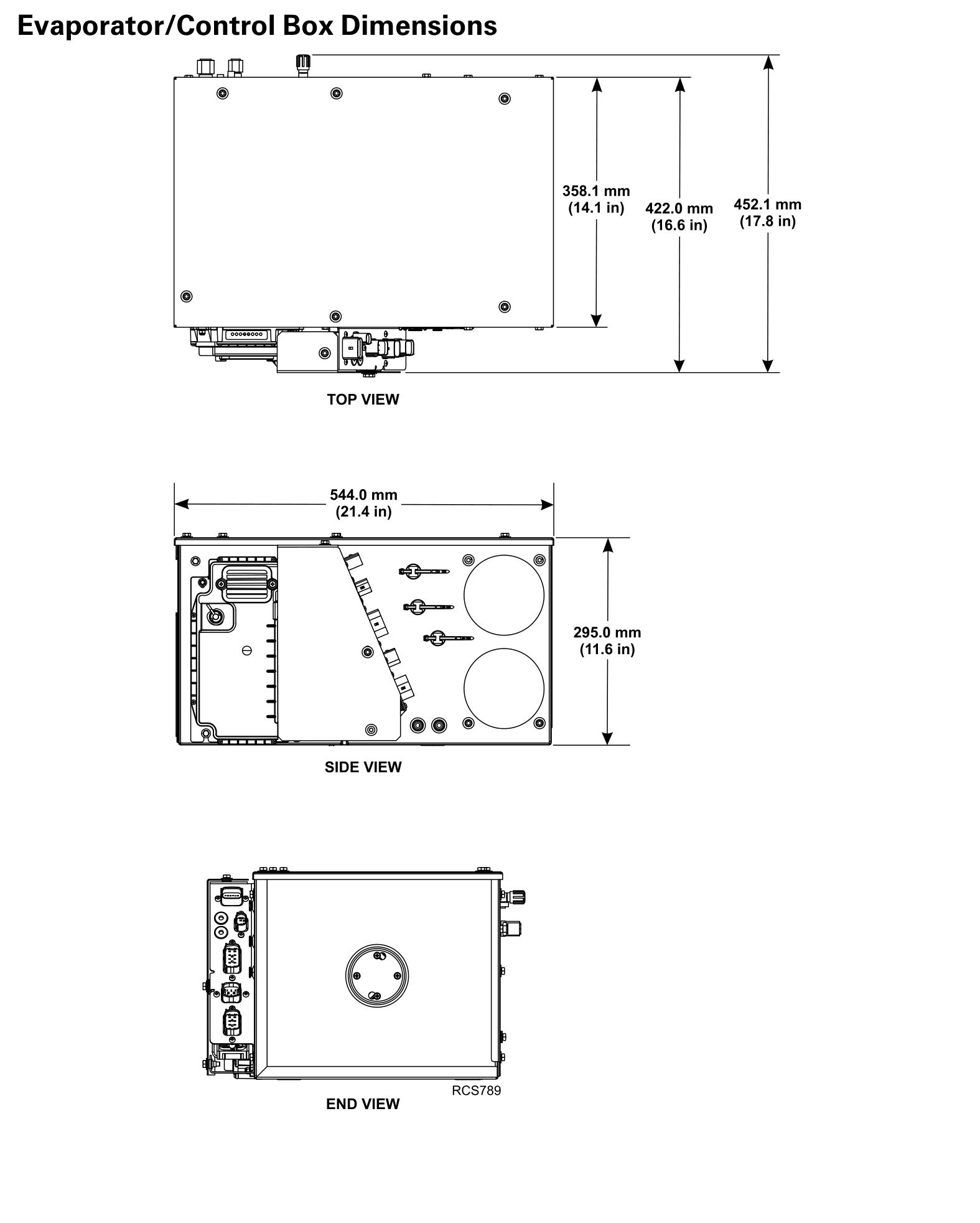
The illustrated side view is 21.4 in (544 mm) long and 11.6 in (295 mm) high. Review the top view for projections, connections and additional space.
Sleeper wall
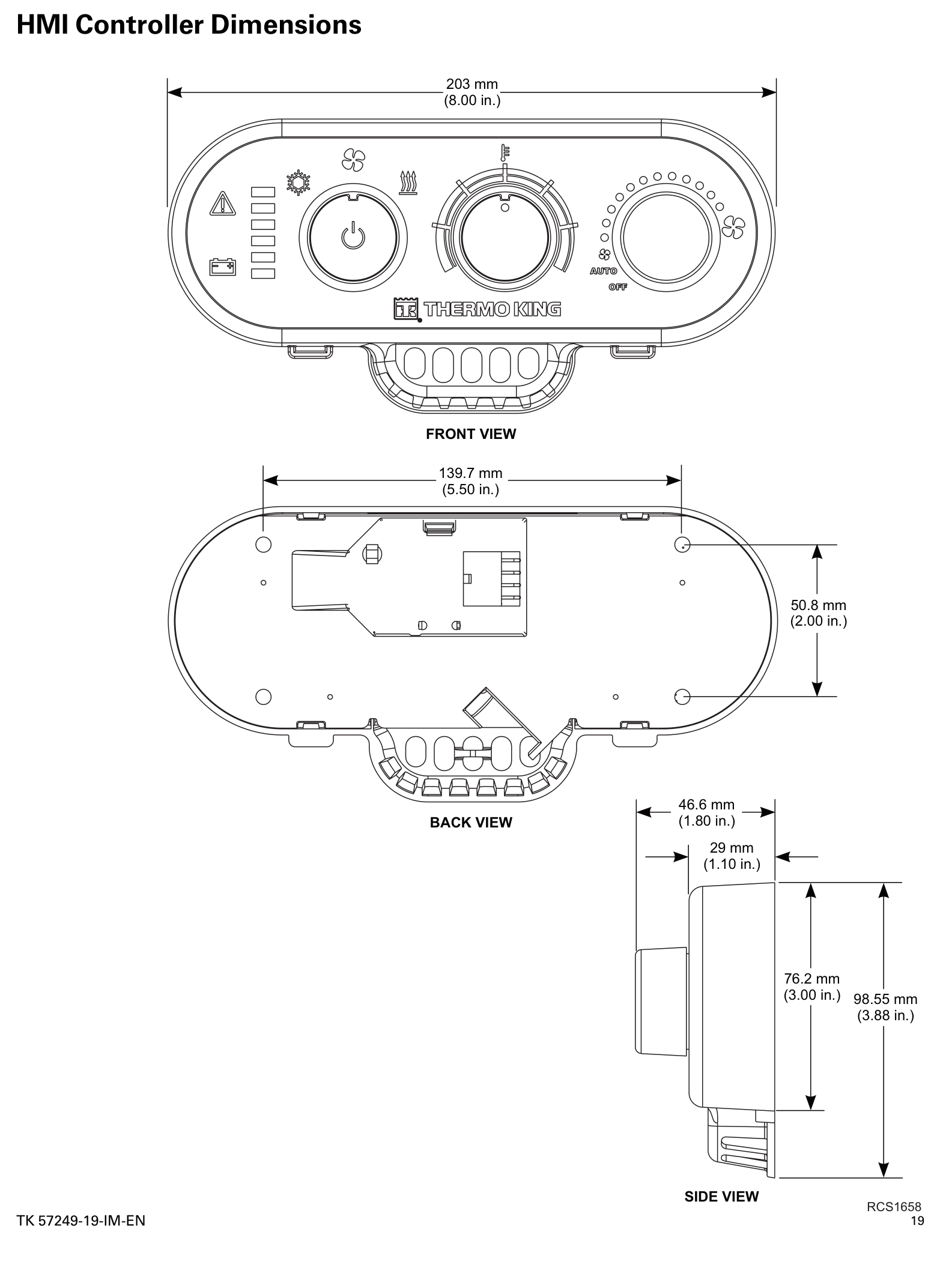
The face shown is 8.00 in (203 mm) wide. The drawing also shows the rear mounting and connector projection.
Sleeper storage / tool compartment
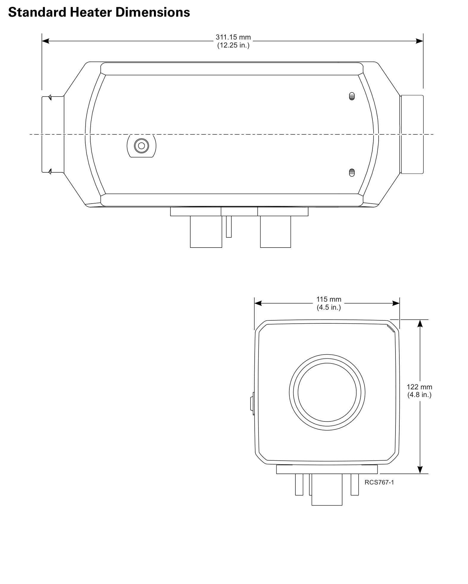
Standard heater: 12.25 × 4.50 × 4.80 in. High-output heater: 14.80 × 5.51 × 5.90 in. These are fuel-fired options for the electric APU.
Available charging option
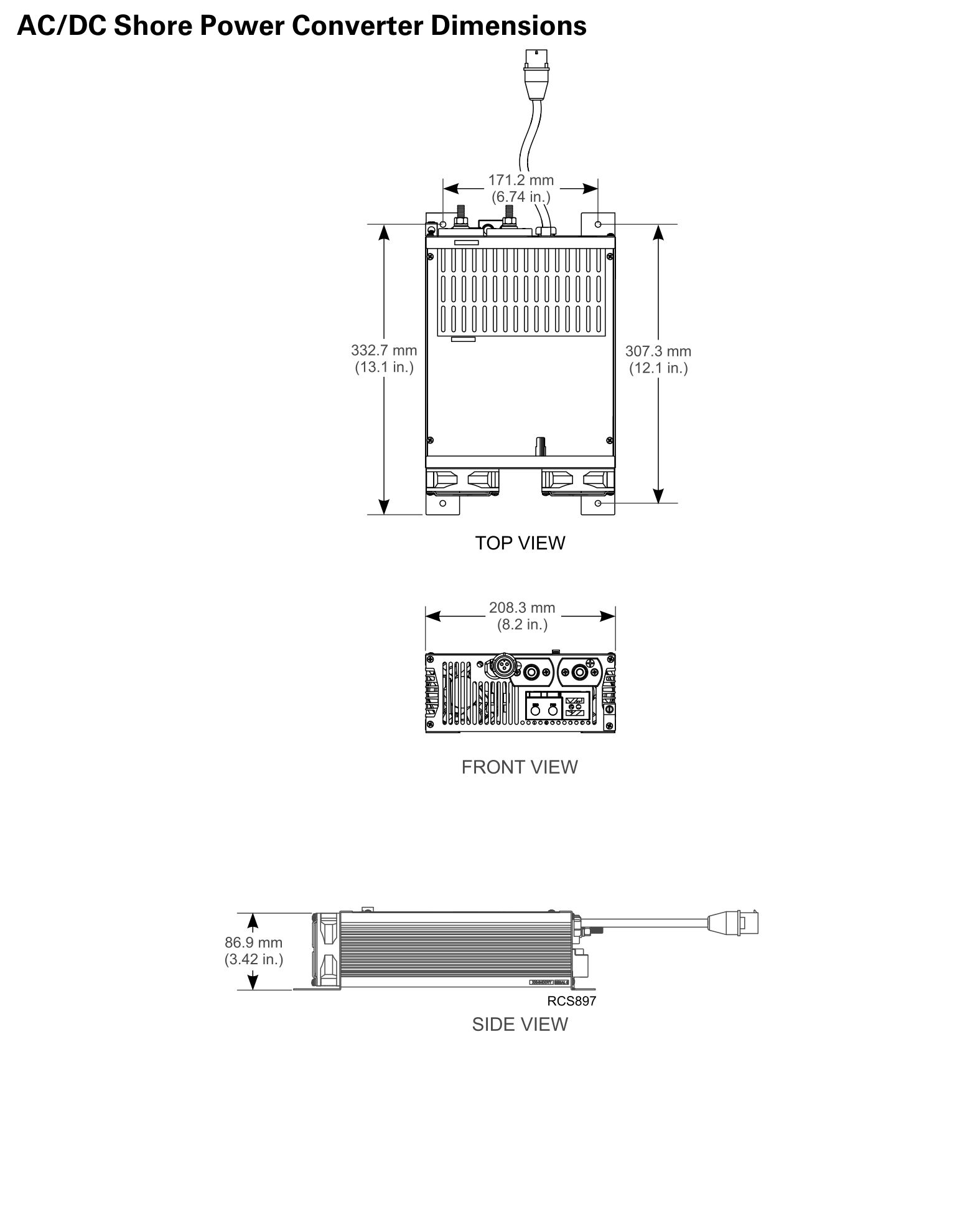
The drawing shows 13.1 × 8.2 × 3.42 in (332.7 × 208.3 × 86.9 mm), including the illustrated mounting span. Leave space for cables and ventilation.
Available electrical option
The drawing shows a 13.3 × 8.1 × 3.5 in body (337.8 × 205.7 × 89 mm); the front mounting width shown is 8.7 in (221 mm). Check cable and cooling space.
Before you choose a location
These are planning dimensions. Actual mounting, service access and clearances depend on the truck, configuration and components selected.
Measure available space around the fuel tank, fairings, steps and other equipment. Identify the mounting side and possible obstructions.
Look for space for the condenser, its fittings and unobstructed airflow. Account for other equipment already mounted behind the cab.
Check the space for the evaporator, heater and any power equipment, including space for ducting, wiring and service access.
Consider an ATD, inverter, shore power, exhaust, hoses and brackets. Your installer will confirm the final layout and required clearances.
Keep the details handy
Open either manufacturer excerpt below, or download a copy to share with your sales representative.
Choose the correct system for your truck.
Read the document without leaving this page.
Select a document to begin.
We’re here to help
Bring your measurements and truck details to our team. We’ll help you work through the equipment and installation options.